The Young Clockmaker
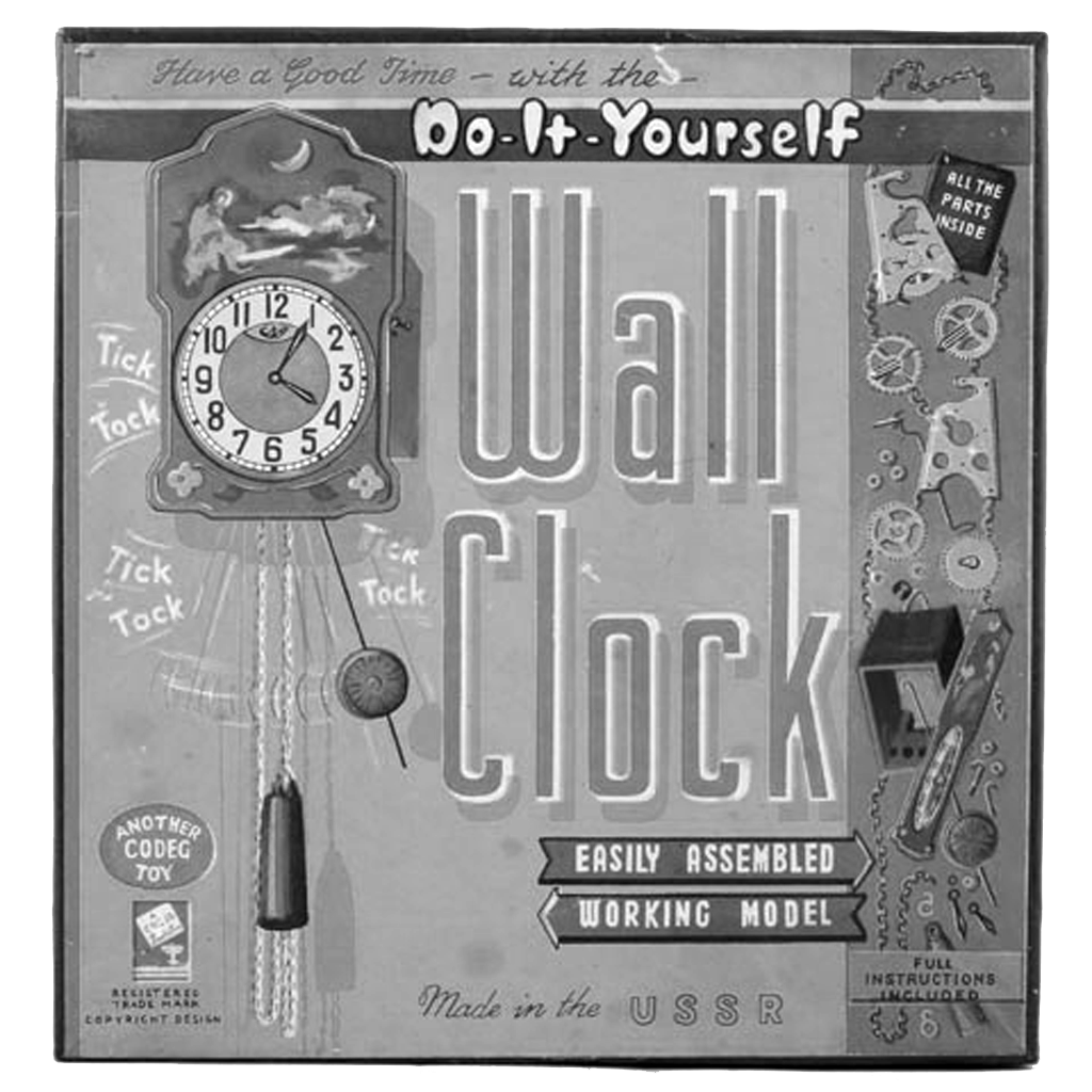
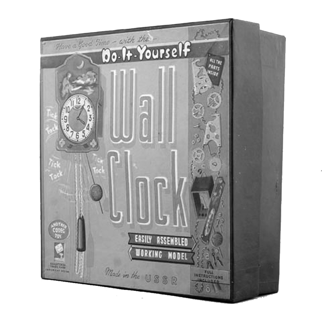
«Do-It-Yourself» kit for building a tin-face khodiki pendulum clock with 18-page instruction book that appears to have been written and printed in USSR.
British firm «Cowan de Groot» imported and sold this kit under the trademark «Codeg».
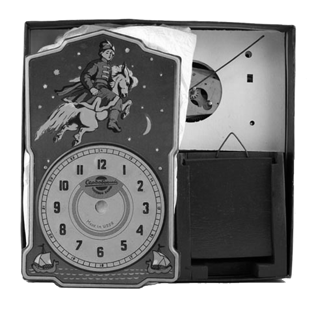
Clock face features an image of «Ivan the Fool on the Humpbacked Horse» from the fairy tale «The Humpbacked Horse» by Russian poet Petr Yershov, 1815–1869.
Face measures 20 x 12 cm.
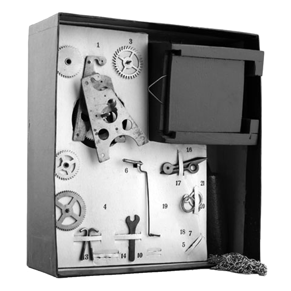
polytechnic toy «The Young Clockmaker»
|
Construction set «The Young Clockmaker»
Rules for assembling and dismantling
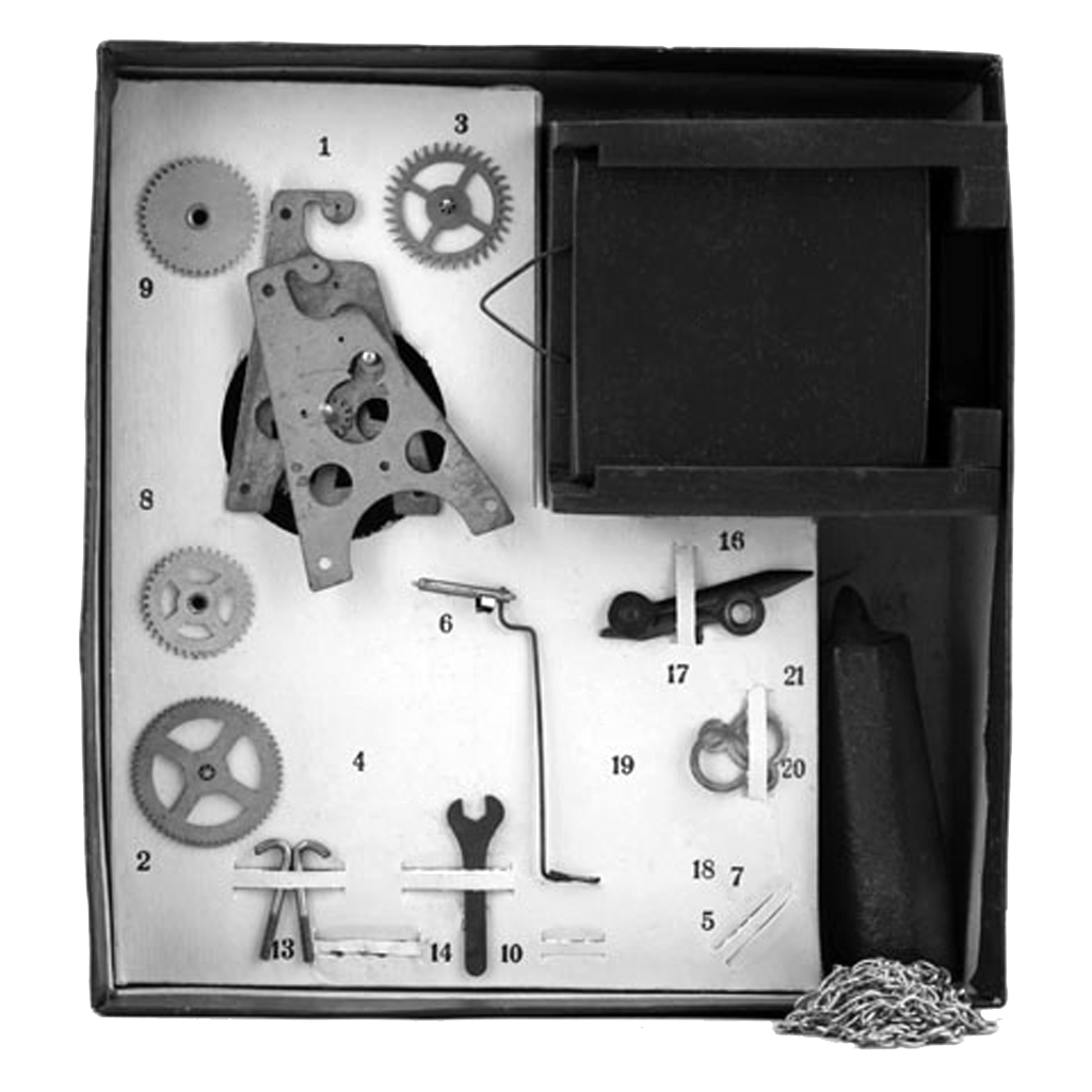
The practical construction set «The Young Clockmaker» is a toy intended for children of school age.
«The Young Clockmaker» acquaints them with the simplest type of clock-work and consists of a set component parts and permanently joined parts from which a working clock for children is made.
A weight provides the motive power.
The instructions acquaint the young clockmaker with the rules for assembling the children's clock.
Prior the assembling it is necessary to acquaint oneself with the names of the details and component units as well as with the pictures.
When assembling and dismantling: the clock avoid hitting any parts so as avoid bending or damaging them.
Procedure for assembling the clockwork
Take Component 1 — Front Plate and Pillars with attached Centre Wheel and Pulley Wheel — and place it in such a way that the three Pillars g, d, e will point upwards, see Figure II.
Component 2 — First Pinion Wheel — Insert it with the short end of the pinion into opening a in the plate.
Component 3 — Escape Wheel with Pinion — insert the long end of the Pinion into the opening b.
Take component 4 — the Back Plate — and attach it to all the three pillars g, d, e, of Component 1, see Figure I.
Ensure that the top ends of all three wheel shafts enter the openings a, b, w in the back plate.
Take one of the nuts — component 5 — and screw it on one of the pillars as shown in Figure III.
Then screw on the following two nuts.
In order to secure the plates firmly, tighten the nuts with the spanner supplied with the construction set.
Test the centre wheel and pulley wheel by turning the protruding end of the centre shaft, making sure that all the wheels turn easily and smoothly.
Now place Component 6 — the Pallets — in its place as shown in Figure IV.
Bend the lobe of either left or right plate, indicated in Figure 4 by the letter i, outwards so as to enable you to insert the Pallets, Component 6, between them.
Insert the Pallet shaft into the openings in the lobes, indicated by the letter g as shown in Figure IV.
After making sure that component 6 has been inserted correctly, straighten the lobes of the plates which you have bent.
Make sure that the Pallet Shaft is not squeezed too tightly between these projections, lobes.
Now place the clockwork in the position shown in Figure V.
Slip Component 7 — the washer of the minute wheel — on to the shaft which is indicated in Figure V by the letter k.
Slip Component 8 — the Minute Wheel with Pinion — on to the same shaft, see Figure V.
Now slip Component 9 — the Hour Wheel with the Tapering Tube — on to the shaft of the Centre Wheel, indicated by the letter l as shown in Figure V.
Having done this it is necessary to attach Component 10 — the Broach Collar — into the groove at the end of the shaft k.
First push the aperture of the washer against the neck of the shaft.
You must move it in the direction of the arrow shown in Figure V.
Then apply something hard against the washer so that the shaft will slide past the narrow part of the aperture and fixes itself in the centre of the washer.
The assembling of the clockwork is completed by harnessing the chain, Component 11, on to the teeth of the pulley wheel, see Figure V.
Put the end of the chain, from below, between the right pillar and the pulley wheel and pull the chain through to half its length.
Then pass the same end of the chain between the teeth of the pulley wheel, they are indicated by the letter m in Figure V, and the Pinion of the First Pinion Wheel, Component 2.
Finally, put the end of tne chain between the pillars and draw it downwards as shown in Figure V.
This concludes the assembly of the clockwork.
Oiling
The clockwork is oiled before it leaves the factory.
Subsequent oiling you must do yourself, in the following manner: dip the clean end of a match stick or wire in watchmaker's oil and apply it to openings a, b, w and g in the plates into which the shaft ends are inserted.
Assembling of the clock itself
Place the casing of the clock, Component 12, before you, see Figure VI.
Take the assembled clockwork with the chain and hold it in such a manner that the Pallet fork with crutch z, see Figure IV, ts directed inwards into the casing.
Pull the ends of the chain through the openings in the bottom of the body and pull the chain through gradually and fit the clockwork into the body.
After placing the clockwork inside the body it is necessary to attach it to the bottom of the body by means of hooks, Component 13.
Fix the hook, Component 13, into the little opening in the bottom of the body in such a way that the bent end of the hook catches the pillar of the clockwork while the straight end protrudes from the bottom.
Slide a washer, Component 14, on the protruding end and screw a nut on to the end, Component 5.
While you do this hold the hook on to the pillar of the clockwork with the other hand.
Follow the same procedure with the other hook.
After this adjust the clockwork within the body so that the front plate will be parallel with the face of the body.
The front plate must find itself 4 to 5 millimetres inside the box.
Now, holding the clockwork with one hand, tighten the nuts on the fastening hooks with the spanner.
Now put Component 15 — the Dial with the Dial Base — into position, see Figure VII.
Make sure that the shaft of the Centre Wheel is exactly in the centre of the opening in the Dial and also that the Dial is straight in relation to the body.
Press the dial into position.
If the dial is not attached firmly to the body, bend the ears u inwards as required.
Now lock the catches s on the body into the ears u on the Dial Base, see Figure VII.
Take Component 16 — the Hour Hand — hold it with the projecting side of the socket towards the dial and place it loosely on to the tapering tube of the hour wheel, indicated in Figure V by the letter r, which sticks out from the centre of the dial.
Screw Component 17 — the Minute Hand — fingertight on to the projecting end of the shaft of the Centre Wheel.
In order to fix the minute hand finally, screw Component 18 — the Minute Hand's Nut — on to the same shaft.
The nut must be screwed on tightly.
Before securing the hour hand adjust both it and the minute hand to read 12 o'clock.
Having done this take a blunt knife or a nut wrench, place it between the handles close to the shaft and press on the hour handle in the direction of the dial.
The handle will then fix itself firmly on to the tapering tube of the hour wheel.
Now hang the pendulum — Component 19.
Take the clock and remove, by pressing, the back wall from the body.
Now insert the hook end of the pendulum — Component 19 — into the square opening at the base of the casing and put it through the loop of the Pallet Fork Crutch.
Then hook it on to the rocking device v, shown in Figure VI.
Replace the back wall and hang the clock on a straight wall.
Attach Component 20 — Loop for the Chain — to the left end of the chain and Component 21 — the Loop for the Weight-to the right end of the Chain, see Figure VIII.
Hang the weight on Component 21 as shown in Figure VIII.
The assembling of the clock is completed.
Adjust the hands at the required time and start the pendulum.
Listen to the sound of the clock's movement.
The sound must be the same whether the pendulum moves to the right or to the left.
Try to achieve this even ticking of the clock by moving the clock slightly to the right or the left as required.
If the even movement of the clock can be achieved only by greatly distorting the clock's angle on the wall, it will be necessary to open the back wall of the body and bend the Pallet's Fork and Crutch 3 in Figure IV, in the direction of the distortion of the clock's position on the wall.
Having done this, check the exactness of the clock's timing against another clock or the radio time signals.
If the time goes fast, lower the pendulum's bob somewhat a long its rod.
If it goes slow, raise it.
The clock should be wound up once a day by pulling the weight up by the left end of the chain.
For dismantling the clock the above procedure is reversed, starting with the unhooking of the weight and the two loops and ending with the separation of the plates and the dismantling of the wheels.